Topic: HP-65 repairing

Sure Jacques, do you want to create a forum category "HP-65 Hardware" in the hardware section ?

Thanks for the in going advice, I have ordered some PN3646 transistors, but they're coming from the US, it will be a week or more before I get them :-)

In the meantime, I'll check the board thoroughly so make sure there are no shorts.

Cheers,
John


--- On Mon, 21/9/09, HP35 <xxx@jacques-laporte.org> wrote:

From:  <xxx@jacques-laporte.org>
Subject: Re: HP 65 repair information ?
To: "John Robinson"
Received: Monday, 21 September, 2009, 9:19 PM

Hi John,
If you don't mind, why don't we continue this discussion on the forum of my site?
It needs a little animation! wink


I could clean up the circuit board pads etc, and I'll start again.

Won't do no harm!

How critical do you think it is to use the fairchild PN3646  for the second transistor ?, should a 2N3904 be a reasonable substitute ?

I attach an HP internal replacement chart.
Listen, I'm very practical they don't put two 4-550, so I assume there is a difference.


The equivalence for the 4-550 is 2N3904 and the second is PN3646 (Fairchild).

It has been tested with success by myself and friends.

Take good fresh parts, test them.
Ge diode gives on the controller (diode position) = .200 .210
Transistor 4-550 = .560 black on base, red on  emitter and .660 red on base, black on collector (1 if you inverse probes).
Might be slightly different with another controller.

Put them on circuit.
If no avail, recheck to see what happened.
If there is somewhere a permanent problem (shorting circuit) : each time you build the circuit, you gonna blow it!

Cheers,
Jacques.


Le 21 sept. 2009 à 08:03, John Robinson a écrit :
Hi Jacques,

Thanks for the reply - appreciated as always.

I know your spice page very well now, I have been referencing that page for some time now.

With the board, I replaced the transistors, diodes, and major caps + 2nF cap, and it still wouldn't work :-( So I have now removed all DC-DC converter components, so I could clean up the circuit board pads etc, and I'll start again.

It's interesting what you way about the transistors though, as I had been using 2N3904 for both Q1 and Q2. I used them on my similation of the DC-DC converter, and on the previous board I was repairing, and they seemed to work fine.

How critical do you think it is to use the fairchild PN3646  for the second transistor ?, should a 2N3904 be a reasonable substitute ?

Maybe I should by some PN3646  anyway.

Thanks
John


--- On Mon, 21/9/09, HP35 <HP35@jacques-laporte.org> wrote:

From: <xxx@jacques-laporte.org>
Subject: Re: HP 65 repair information ?
To: "John Robinson"
Received: Monday, 21 September, 2009, 2:26 AM


Hi John,

The HP-65's DC-DC is not difficult to fix if you follow a good working sequence
see here
../PowerUnit_SpiceDeck.htm

check the diodes (modern equivalence is 1N270)
check the transistors
2 NPN transistors labeled 4-550 (switching) HP Part 1854-0550 and 4-094 (regulation) HP part 1854-0094,
most of the time the 4-550 is burnt when no oscillation
Equivalence for the 4-550 is 2N3904 and the second is PN3646 (Fairchild).
check the big Caps (60uf and 15 uf).

The other passive parts are out of cause.

required for the oscillator

2 NPN
le LRC cell (torroidal, 2nf cap and 47ohm),
the big caps 60uf and 15 uf.

The 22uf and 2.2uf caps are for filtering (but I never seen them causing trouble).

But you don't need to remove all the parts.
In 80% of the cases : changing the oscillator 4-550 and a diode (mainly d8) is enough.

All this is on the lower part of the main circuit board. The diodes to check are between the Mostek ROM 1818-0073 and the transformer.

Take care,
Jacques.


Le 17 sept. 2009 à 01:34, John Robinson a écrit :
Hi Jacques,

Since I last contacted you, I have acquired (bought) a few more HP65 logic boards in various states of completeness, all are reported to be non-functional. I tested the complete boards and they are all non-functional.

One of the boards, was sold to me as "used to work - probably not much wrong with it", so I thought this board is the best one to start attempting repair.

I found the DC-DC converter on this board is not working correctly, in fact the oscillator is not oscillating. I replaced both transistors, all diodes, and capacitors, and it's still not oscillating :-( I even swapped out the toroidal transformer, with no difference !!

I want to remove all power supply components from the board, and put only the components back on that are required for the oscillator to function.

I wanted your advice on which components are required. From what I understand, I need 7 components :
1. Toroidal transformer
2. The transistor (with collector connected to transformer
3. The 2nF capacitor
4. The 47 ohm resistor
5. The 15uF capacitor
6. The 60uF capacitor
7. The 1Kohn resistor

Is this correct ? or do I need more or less just to get the oscillator oscilalting :-)

Thanks for you help

Cheers,
John
2

Re: HP-65 repairing

Hi Jacques, is there anyway I can attach a file to a forum posting ?

Thanks
John

Re: HP-65 repairing

You can create links to other documents or to images, photos ....
See the link BBCode

HP replacement part cross reference

4

Re: HP-65 repairing

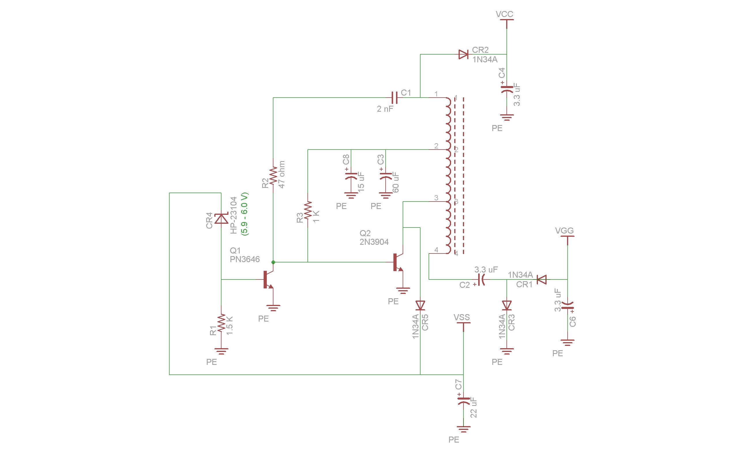
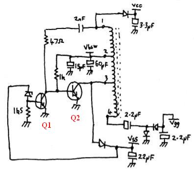
Hi Jaques, I want to check my understanding of the location and function of the twp transistors in the 65 DC-DC converter. I haven't ever seen a circuti diagram of the 65 DC-DC converted with labels on any of the components, do for reference, I have taken Tony Duells drawing, and labelled the transistors Q1 and Q2, you can see the diagram at :


http://home.comcen.com.au/therobinsons/dcdc2.jpg

Now, as I understand it, Q1 is the 4-094 and Q2 is the 4-550 - true ?

Q1 can be replaced with the fairchild PN3646 and Q2 can be replaced with the 2N3904 - true ?

Q2 forms the basic oscillator, and Q1 forms the voltage regulator - true ?

Thanks
John

Re: HP-65 repairing

Hi John,
I have no HP-65 'open' at the moment and I don't want to have to restore the black label of my one and only 65, to make a macro photo.
Maybe a kind reader ?
But the switcher (oscillator) 4-550 (Q2) has its emitter grounded and the collector is wired to the toroidal transformer.
The schematic you just posted is good.
The regulator 4-094 is connected to the base of the former by its collector.
On its base a 1.5K and a zener diode.

More, On the 55, 45 and 65 logic boards I have seen so far, the indications 4-550 or 4-094 are written on the transistor.

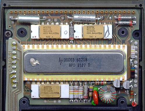
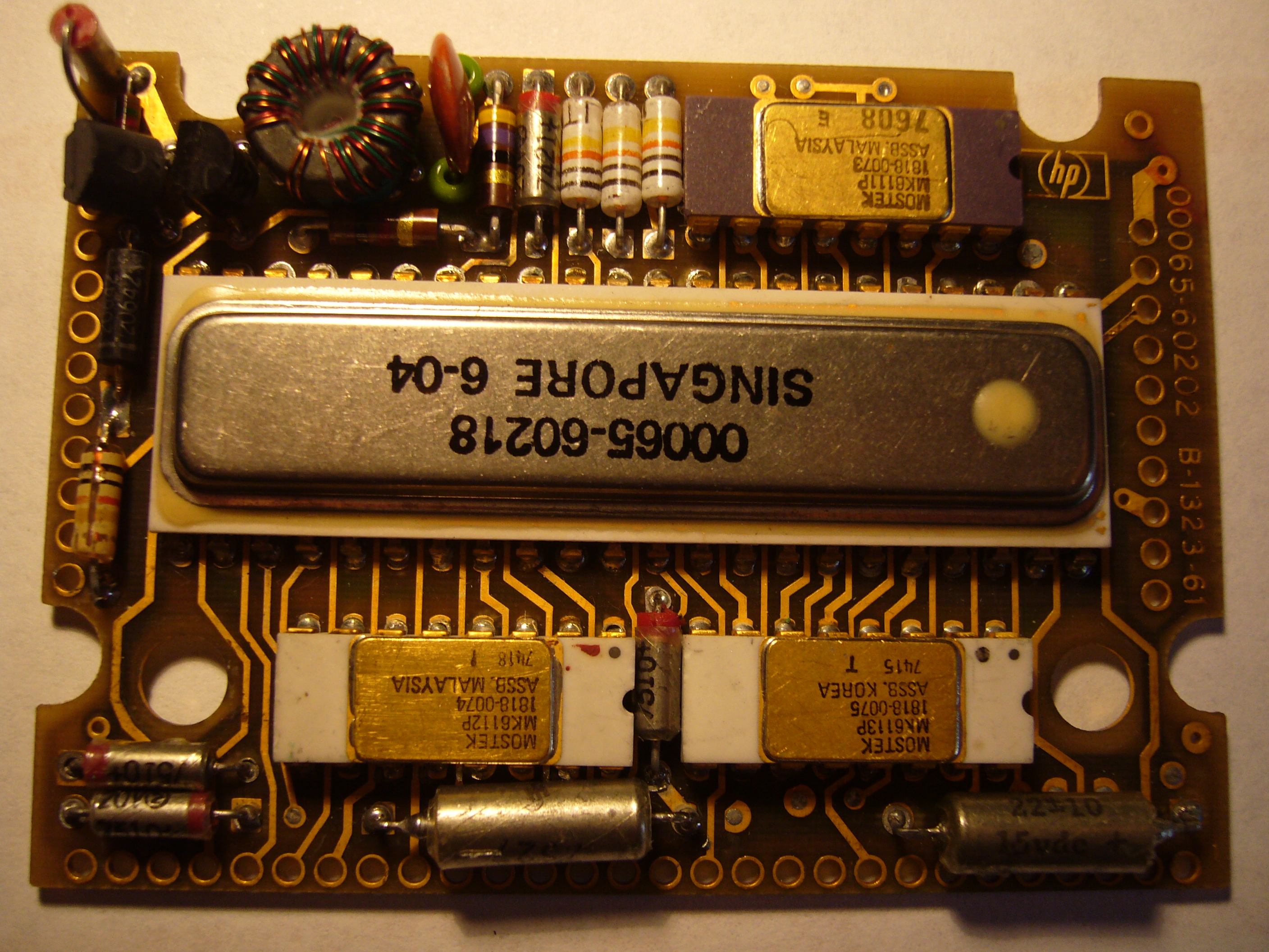
From memory and with the help of a photo from 'The Museum of HP Calculators', looking the main circuit board, from left to right below the hybrid circuit, there is a Mostek ROM MK6111P (type 1818-0073), 3 Ge diodes, 1 electrolytic cap, the 47 ohms (yellow, violet, black), the 1K ohms (brown, black, red) // to hybrid, the 2nf cap (red with green pearls), the toroidal transformer and the 2 transistors the switcher (Q2) and the regulator (Q1) ; at right the zener (followed by the Vss diode) and the 1.5K resistor (brown, green, red) to ground.

http://www.hpmuseum.org/65cpu.jpg

That should be close, but check with your board.   

I'll try anyway to get a better photo for you, but maybe you can contribute with a closeup of your board  wink

6

Re: HP-65 repairing

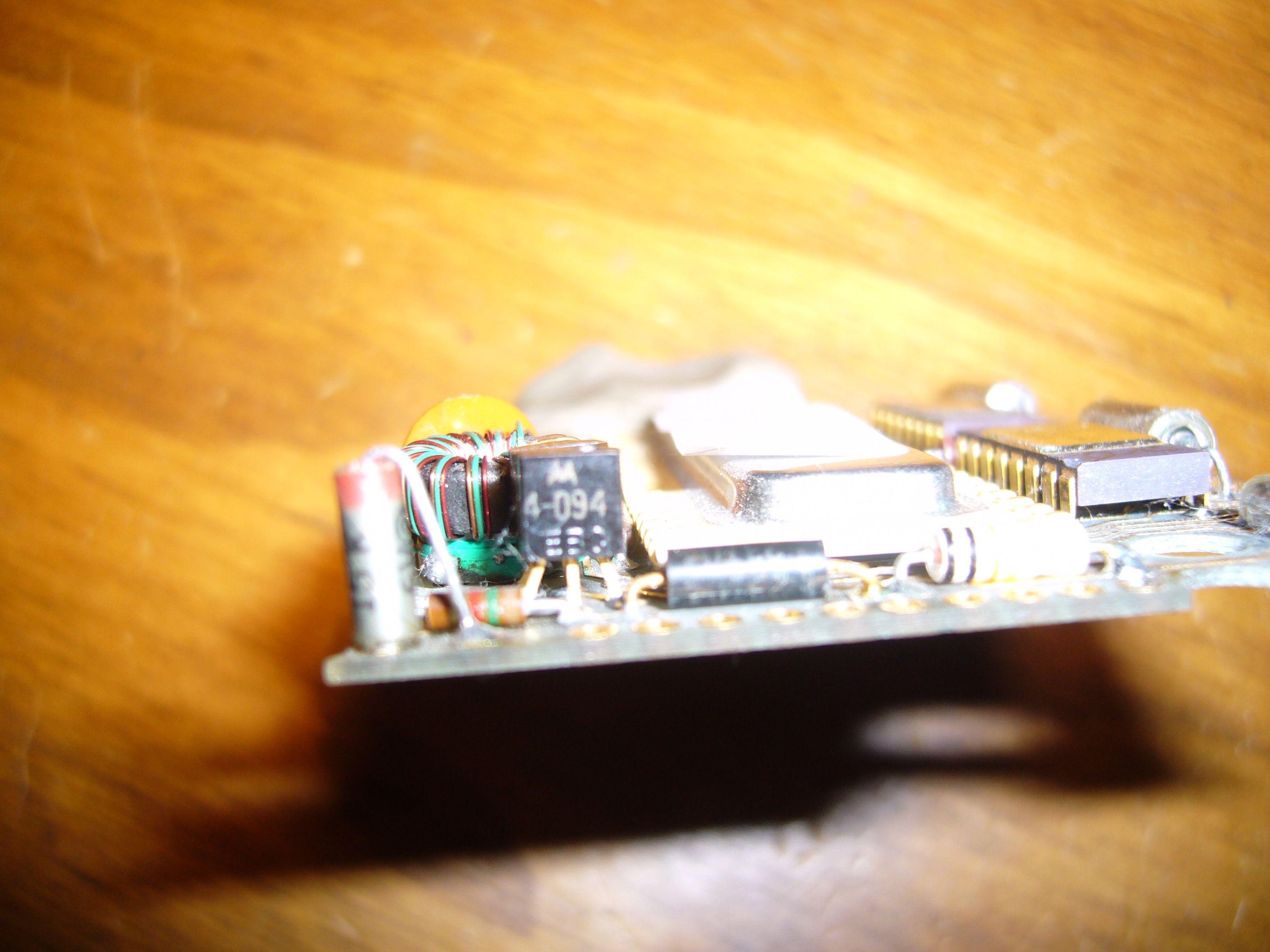
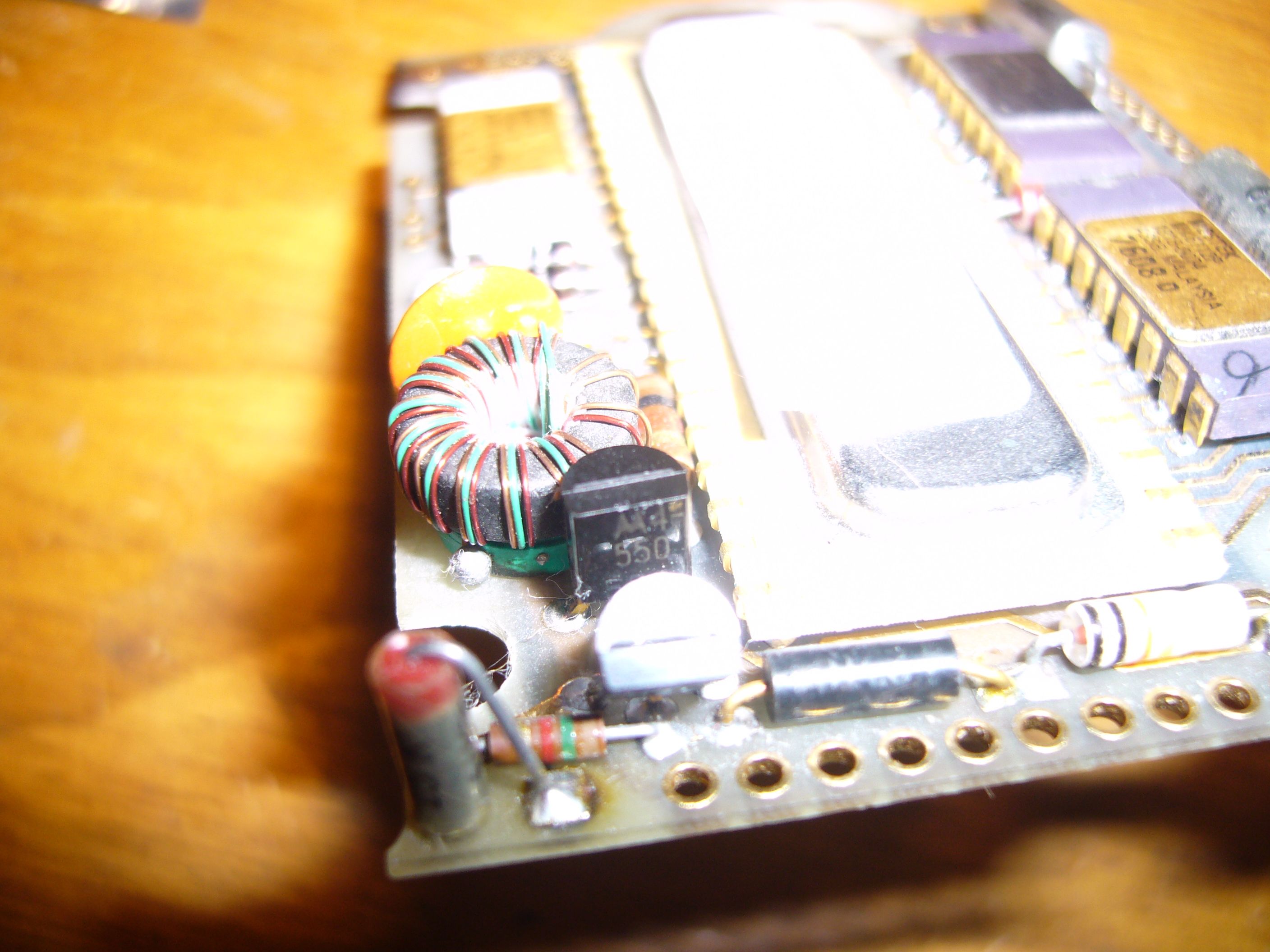
Hi Jacques, thanks for the reply. I think this is what causes my confusion, as on all the 65 boards I have, the transistors are marked Q1 as 4-094 and Q2 as 4-550, I have taken a couple of pics of the transistors from a 65 board I have with workking DC-DC converter,

http://home.comcen.com.au/therobinsons/q1.jpg
http://home.comcen.com.au/therobinsons/q2.jpg


It seems that the transistors used on the 65 may not always be the same as those on the 45 and 55. So I guess the question is, what is a suitable replacement for the 4-094 ?

Cheers,
John

Re: HP-65 repairing

JR wrote:

Hi Jacques, thanks for the reply. I think this is what causes my confusion, as on all the 65 boards I have, the transistors are marked Q1 as 4-094 and Q2 as 4-550, I have taken a couple of pics of the transistors from a 65 board I have with workking DC-DC converter,

http://home.comcen.com.au/therobinsons/q1.jpg
http://home.comcen.com.au/therobinsons/q2.jpg

It seems that the transistors used on the 65 may not always be the same as those on the 45 and 55. So I guess the question is, what is a suitable replacement for the 4-094 ?

Cheers,
John

Hi John,

The 45 and 65 use the same pair of transistors. The 094 replacement is the PN3646. The 550 replacement is the 2N3904. Both NPN. I don't have a 55 in front of me but I am quite sure it is the same.  The 67 appears to be different, using 4-668 (M621) and 4-071 (M611), not sure what the modern equivalent for these are.

-- Dan

Re: HP-65 repairing

Hi John,
Here is a more documented answer.
As you took closeup of your boards, the black labels of my dear HP65 will remain intact, thank you.
On your photos, the references of each transistor are marked clearly, so I'm not sure I have understood well your question.
But anyway, I assume you want me to make to put some light on the point. ok.

Except the case of the 35, the DC-DC converter on the red led HP calculators used a pair of NPN transistors : a switcher and a regulator.

HP published a cross reference of replacement parts ; but it is not complete.
Anyway, here is what I have seen and sometimes photographed.

HP-45 switcher 4-550 (HP part 1854-0550), regulation 4-094 (1854-0094)
see my photo below
http://www.jacques-laporte.org/forum/photos/HP45-PSU.jpg

HP-55 switcher 4-550 (HP part 1854-0550), regulation 4-094 (1854-0094)
see my photo below
http://www.jacques-laporte.org/forum/photos/PSU-55.png

HP-65 switcher 4-550 (HP part 1854-0550), regulation 4-094 (1854-0094)
see your photos

HP-25 (and HP-21) switcher 4-550 (HP part 1854-0550), regulation 4-071 (1854-0071)
see my my photo below
http://www.jacques-laporte.org/forum/photos/PSU-25.png


HP-67 and HP-97 switcher 4-668 (HP part 1854-0668), regulation 4-071 (1854-0071)
HP-97 service Manual

etc 

The HP part 1854-0094 is listed in the HP replacement part cross ref (lucky we are, it's not always the case) : equivalence PN 3646 (The 4-550 replacement being the 2N3904).

http://www.jacques-laporte.org/forum/photos/HPreplacementpartXref.jpg


Have a look also at the HP-65 layout schematic from the HP Journal may 74.

http://www.jacques-laporte.org/forum/photos/HP65-layout.png

Clearly Q2 the switcher is the one close T1 and the regulator Q1 is connected to the Zener CR4 and the 1.5K R1.

Now, If the question was : could I use two 3904? the answer is clearly no.
Having compared the specs and spice models of both they are far from identical.
Q2 will switch current at high frequency while Q1 will just do the biasing of Q2 with the feedback of the zener.

To help you fixing your unit ; I assume the 4-550 is dead ;  could you check the 4-094, just in case (check both BE BC junctions).
And also the Vss Ge diode CR5 on the HP schematic.

Hope all this will help,
Cheers,
Jacques.

ps: by the way, you have under the eyes a 65 main logic board ;
could you please place on your hand schematic the references from the HP layout wink
It could help for further discussion.
Thank you.

9

Re: HP-65 repairing

Hi Jacques, Thanks for the clarification. I was definately confused, as I incorrectly thought that the DC-DC converters using 2 NPN transistors used the 4-550 and 4-071, but now reading your 35 DC-DC converter, and spice pages I see I was wrong.

The schematic I labelled was from Tony Duells drawing from the PPC CDROMs. Until I saw your HP-65 layout from the HP journal, I didn't know what the standard component labels were for the 65. I will redraw Tony's circuit diagram using a cad package, and use the correct components labels, and post that to this forum thread.

Oh, also, when I built a replica of the DC-DC converter on some prototype board, I used 2 x 2N 3904 transistors, and it works pretty well. Also, I have one 65 logic board where I used 2 x 2N3904 and it also works pretty well. But I will take your advice and use the 3646 :-) I have some on order now.

Cheers,
John

Re: HP-65 repairing

Ok, happy it works for you smile

But be careful, HP ever used 2 switchers 4-550 whatever the PSU circuit.

Thank you for drawing a referenced schematic ; if you can add a closeup of you main logic board, I'll be glad to publish it on my PSU page.

Now you're up and running for the rest of the repairing!

11

Re: HP-65 repairing

Hi Jacques,

I finally finished drawing the 65 DC-DC converted schematic using a CAD package (Eagle PCB). I used the component names as used by HP in the logic board layout from the HP journal. Here is the schematic :

http://home.comcen.com.au/therobinsons/hp65dcdc.jpg

Also, I took a close up pic of a 65 logic board for you too, here it is :

http://home.comcen.com.au/therobinsons/65logicboard.jpg

I have two other pictures of other 65 logic boards too, which are slightly different, with the difference being the packaging of the hybrid chip. If you want those as well, I shall make the available to you.

Cheers,
John

12

Re: HP-65 repairing

I just realised the jpg of the schematic is a little unreadable, so if you too find it hard to see, try the pdf version at :

http://home.comcen.com.au/therobinsons/65DCDCconverter.pdf

Cheers,
John

Re: HP-65 repairing

Thank you John,
I'll check all this material later this week.
At first sight, the HP-65's PSU looks much like the 45's one.

I have answered to your question about testing the Classic LED segments on another forum.

http://www.jacques-laporte.org/forum/photos/ClassicLedTesting.JPG

We can discuss this interesting point here, if you want.

The Classic LED voltage drop is 1.7 V, so with a 3.6 V DC supply and a 82 ohms resistor as on the breadboard, you'll get a current thru the LED of 23ma.
That's why it's bright.

To be conservative, testing them with 200 or 250 ohms would be ok (those LEDs were not designed to be operated on DC but on pulsed current).
Don't reverse the polarity (check out the cluster pins!) : LED's are not generally able to withstand reverse bias.
But you can test all the LEDs segments, the Anode Driver and Cathode Driver in one operation (see my page about the display).

Last word, Anode and Cathode Drivers are bipolar hence rather robust. If you have a display problem, check the LEDs first and the A&R next.

Cheers,
Jacques.