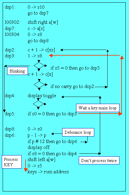
The display and wait routine
The following algorithm is the basic loop of the software: the calculator is displaying the previous result and waiting for another key to be actuated.

The loop is entered after a keystroke has been processed and after the output has been formatted, register A loaded with the number to display and register B loaded with the “display mask”.
Three bits are used to control the loop:
- status bit 0 (S0) is hardwired in the C&T and is set to 1, when a key is down,
-
status bit 8 (S8) is used by the firmware to test if the key presently down has
already been processed (since a routine may be finished before the user release
the key).
If S0=1 the key which is down may be or not a new one, so the bit S8 is checked.
If it is a new key (S8=1), the control is passed to the key routine.
- Status bit 5 (S5) is used to blink the display in case of error.
Let’s detail this crucial loop.
Returning from math routines the entry point is at address 0333 (333 Rom 0) ;
0333: jsb of13
1 -> s7
fst2zx: jsb dsp1
jsb fst3
go to den2
The control jumps to “disp1” using a “jsb” instruction (subroutine call instruction).
A second entry point is 0302 from Key code 54 (arc prefix key).
00054: 1 ->
s10
go to l00302
A third is 0277 coming from 0001 on error to display a blinking zero.
000277: jsb of12
1 -> s5
go to fst2zx
fst2zx: jsb dsp1
.../..
But in the general case, the main entry point is at label “dsp1” (see the trace run for the digit “9” entry from PWO).
 First
thing at 0367, flag 10 is reset to wipe “arc prefix” key use (if any)
(instructions:
dsp7: c -> a[s] dsp7
are explained below).
Next the 2 key flags controlling the routine are initialized:
- the first time through the routine, flag S8 is set to zero meaning "no previous key processed"
- flag s0 is set to zero meaning “no key down”.
By setting S0 to 1, the C&R signals that a key is down (pressed).
S8=1 is the indication (kept by the firmware) that the “key down” (flagged by S0=1) is a new one (a routine may finish before the key is released).
Then control enters at “dsp6” in a “long” time delay (around 14.4 ms) to prevent key bounce from executing a function twice.
At the end of this de-bounce wait, the previous result is displayed (at “dsp4”) and control is passed (label “dsp“) to the basic and inner wait cycle of the machine: “dsp3->dsp5->dsp3) the control is idling waiting for a “key down”.
When a key is pressed, S0 is raised by hardware, and control is passed to “dsp8”: once again a 14.4 ms loop is made, the display is turned off display (0323) and a check is made to clarify if the key just seen down is a new key (s8=1) or the one previously processed (s8=0)
If s8=1: it’s time to prepare to service the key: (label “dsp4”), instruction “shifting left a[w]” is executed (see below), error flag is reset, and control is passed to the key entry point (remember key code is an offset) : "9" key code 062 is an offset (token) in ROM 0 = address 062.
The case of the blinking display is simpler, on error (in math routine) control is passed to address 001 where the instruction is go to 0277. As shown above, a call to “of12” is made clearing X and flag S5 is set to 1 before going in the loop.
If s5 = 1 instruction “c + 1 -> c[x]” at 0312 is executed, and as soon as a carry appears the “display toggle” is executed. Back to “dsp3” (red arrow) where the same process will lead to loop to the next “display toggle”, finally a blinking zero will appear. The only way to escape is to have a “key down” at “dsp5”.
The final mystery in this routine is 3 instructions at the start and at the end of the code:
00302: shift right a[w]
00303: dsp7: c -> a[s]
…/…
00326: shift left a[w]
Remember the way a digit is acquired: 00034: dig1: a + 1 -> a[x]
The normal path is entry 0303 and out 0326, it doesn’t pass at 0302.
The content of register A has to be preserved (to make room for the new digit), that’s the explanation of the “shift left a[w]” at 0326, exiting “dsp6”; the sign of the mantissa will be taken from register C (same number but in normalized form). At address 0210 in the “den” routine, before putting the digit at its place in A, the number in A is re-shaped: instruction “shift right a[ms]” (opposite of instruction 0326) .
But if the “key” we process is a pseudo key (as the arc prefix) we do not pass by routine “den” (no digit to enter), so the “shift right” is done by routine 0302 (instruction shift right a[w]) to anticipate the “shift left” at the end of the routine at 0326.
Note that the instruction at label “dsp7” takes care of the mantissa sign (see here a trace to elucidate this case).
Jacques Laporte
Tuesday, 07 March 2006