The operational stack
HP 35 uses an operational stack and Lukasiewicz notation which are, as noted in the operating manual “the most efficient way known to computer science for evaluating mathematical expressions” (p. i).
In the 1920's, Jan Lukasiewicz proposed a formal logic system which allows writing (on paper) parentheses free mathematical expressions.
 If
the operators are placed before the operands the notation is called “prefix”,
after the operands, the notation is called postfix.
The term “Polish Notation” was coined after the
nationality of Lukasiewicz.
HP used the acronym “RPN” Reverse Polish Notation to refer to the postfix notation.
But RPN, was in fact invented by the Australian computer scientist Charles Hamblin in the late 50s.
Before the HP 35, HP introduced –at the end of the 60’s- the HP 9100 (about this computer see the Steve Leibson’s beautiful pages) which was a 3 level “stack machine” (as opposed to “registers machines").
But the very first computer to implement RPN stack were the English Electric Company's KDF9 (1963) and the Burroughs B5000 (1963). Among the desktop calculator, Friden introduced RPN before HP with the EC-130 (1963).
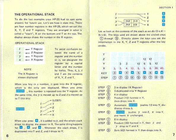
Let’s use the example above (page 6 of the HP 35 Operating Manual) and compute: ((3* 4)+(5*6)=42
In classic algebra, or infix notation, operators appears between operands:
3 * 4 -> 12
5 * 6 -> 30
12 + 30 -> 42
In prefix notation, operators precede operands:
* 3 4 -> 12
* 5 6 -> 30
+ 12 30 -> 42
And In postfix notation they follow operands: 2 3 + -> 5
3 4 * -> 12
5 6 * -> 30
+ 12 30 -> 42
RPN is implemented –in the HP35- in a data structure called a 4 level stack
| T register |
| Z register |
| Y register |
| X register |
The display of the calculator always shows the X register.
As you already know, a “ENTER” key is provided to duplicate a number in X register into Y register. At the same time Y is copied into Z register and Z into T (for top).
When a 2 operand ("dyadic") operation is applied, the stack drops displaying the result in X ; Z drops to Y and T is copied into Z and keep its value (the example p. 7 is very explicit).
Now let’s take the firmware point of view.
1) Instructions to handle stack, auxiliary register M and the display.
Let’s review first the instructions available in the
HP35 A&R programming model, to handle stack operation, including the register M.
Note that this register M is part of the A&R and is not implemented in a RAM
module as it will be in the next calculators (HP 65, HP 25 ..).
- “up stack”: pushes the C register onto the stack and
lift all the stack:
C -> C -> D -> E -> F
X -> X -> Y -> Z -> T
(this second line is the register names for user’ eyes).
- "down stack»: the contrary, but D is popped in
register A and C is untouched:
F -> F -> E -> D -> A
T -> T -> Z -> Y-> A
- “rotate down” to "Roll down" or the Râ
key, to review the stack without losing data and possibly reposition data within
it:
C -> F -> E -> D -> C
- “exchange memory”: will be used to implement the “STO” key:
C -> M -> C
- “recall Memory”: will be used to implement the ”RCL”
key:
M -> C -> C
Clear registers: used to implement the CLR key:
0 -> A,B,C,D,E,F,M
“display OFF”, “display Toggle” : both act on display buffer flip-flop and are used to implement the display and wait loop.
2) Automatic stack handling.
 The
bit flag S7 in the status bit register has a crucial role: raised by a routine
(S7=1) it will force a stack push to be made in the routine “fst3” to which control
is passed on exit of the “dsp” loop (when a digit is entered).
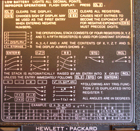
The black label on the back of the machine, tells the whole story.
The stack is raised automatically in two cases:
- a digit entry (possibly part of a number),
- the RCL key pressed.
But to save key stroke, the push does not occur if the entry immediately follows
CLx, STO or ENTER (e.g. “2.55 STO”). Each key routine must set or not the flag S7 to
have or not a stack push.
Let’s look at each case in detail.
3) The STO key.
Entry point 012 which is a relay to 00027
00077: clear status
shift right a[w]
jsb fst2zx
00027: c exchange m
C=00000000000000 M=03141592654000
00030: m -> c
C=03141592654000 M=03141592654000
At 027, the first instruction store the result in register M, and the second copy in C, so the operation is non destructive.
Next, control is passed at address 077 which is the second address of the “ENTER” entry point skipping the push, a “shift right a[w]" is done in compensation of the previous "shift left" (0326) done when control got out “dsp” (see article dedicated to “dsp and wait” loop).
 Remember a digit is entered in the first digit of a[w] and room is left in “dsp”, if no digit is entered (it’s the case with “STO”
key) a correction must be made to reformat register A. That’s what I called
preventive “shift right”.
Control is passed to “dsp” at label “fst2zx”.
No stack push will be made since s7 is = 0 in fst3 when the next key occurs.
See in the trace, the first example "STO digit 1", for details.
Here, I must make a pause to explain the “jsb” versus “go to” problem. The best assiduous readers have surely noticed that sometimes the code is sometimes “jsb fst2zx” (this case) or go to fst2zx (071).
The fact seems curious and it is the reason why the HP 35 ROM is so hard to understand, without a simulator.
There are 78 “jsb” instructions (subroutine calls) in the ROM (V2) and only 8 “return” instructions. Kind of de-structured programming!
The explanation of this fact is the lack of room and the necessity of packing code.
The point is the C&T internal stack responsible for the
“jsb” – return handling is only one level high!
So, if two pushes are made, the first is forgotten.
I couldn't draw the ROM flow chart without using a software. It is not a rare case in software reverse engineering.
4) The RCL key
00010: jsb 00264
go to 00376
A call to 0264 is made at the entry point: it is the
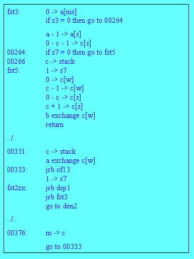
second part of routine "fst3" (see code excerpt above).
The flag S7=1 since there is a result to preserve (see the example 1 of the
trace).
Flag S7 is set to 1 again in fst5: a routine that is not followed by a stack list must put s7 to 0.
As said above, this automatic stack lift takes place after a digit entry unless this entry follows CLx, STO or ENTER.
Next in "fst5" 267-274, a mask for a first digit entry is built in B = 29999999999999.
Control is then the pass to 0376 where the "recall" itself is made (m -> c) and back to the return point 0333.
From this point, a call to “of13” is made to format the output context for the number just recalled and flag 7 is set to 1 again, since "of13" clears the status.
The rest of the route is well known, now, (the control is at the meeting point fst2zx), a call to "dsp1" follows and a call to "fst3" (with s7=1) then we'll go to "den2", if a digit key is pressed. Otherwise, in case of a math function key we'll go to the relevant routine.
5) The ENTER key
If the user wants to apply a dyadic function, he must use the ENTER key between operands: that's RPN.
The entry point is 76 and the code is quite simple this time:
00076: c -> stack
00077: clear status
shift right a[w]
jsb fst2zx
The push is made at 076 and next the status is cleared, then preventive shift right follows and a call to fst2zx is made.
That means we are going into the "dsp" loop and if a digit key is pressed (second number of the dyadic expression (e.g. X Y +), the call to "fst3" will be made with S7=0, one push is enough (see the trace 1 ENTER 2)
6) The exchange X çč Y key
This case is also very simple.
X is in C register and Y is in D.
At entry point 014, we pop the stack down to A (F -> F -> E -> D -> A), next we
go to 331.
stack -> a
go to 00331
There (2 instructions before the return point 333) we push c onto the stack (C -> C -> D -> E -> F), a simple exchange "a exchange c[w]" will do the trick, keeping the rest of the track unchanged.
At entry point:
C=03141592654000
D=01000000000000
E=00000000000000
F=00000000000000
00014: stack -> a
A=01000000000000
C=03141592654000
D=00000000000000
E=00000000000000
F=00000000000000
The rest is well known since, control is at return point 0333 (see trace).
00331: c -> stack
C=03141592654000
D=03141592654000
E=00000000000000
F=00000000000000
00332: a exchange c[w]
A=03141592654000
C=01000000000000
D=03141592654000
E=00000000000000
F=00000000000000
7) The Roll down Key (Râ)
Entry point is 013
goto 00060
It is simply the A&R instruction.
00060 down rotate
00061 go to 00333
8) The change sign CHS key
Entry point is 073
After the preventive "shift right", flag S3 is raised to keep track of the CHS key pressed.
Then control is passed to the "eex" routine if the "CHS" is pressed for an exponent entry (see the explanations regarding data entry).
If it is a mantissa entry then S4=0 (EEX not pressed) and control is passed to routine "chs3", where the value in register C is negated before going to "dsp1" (label "chs3" is the instruction before "dsp1" entry).
00073: shift right a[w]
1 -> s3
go to 00166
00166: if s4 = 0 then go to chs3
a exchange c[wp]
0 - c - 1 -> c[xs]
eex4: c -> a[w]
chs3: 0 - c - 1 -> c[s]
dsp1: 0 -> s10
go to dsp7
9) The π key
As this key routine works like the “RCL” but for the π constant, it found its place in the present article.
The entry point of this routine is 042.
0042 go to 00164
00162 jsb 00264 ; like the RCL key (end of fst3)
select rom 1 ; goto 01166
From there, a call is made to 0264 to take care of the stack push to preserve result in C.
Next control is passed to address 01666 (Rom 1) right in the middle of the trigonometric routine, in which pi/4 constant is loaded, and doubled 2 times to have π .
A special return point is provided at label “rtn11” (s1=0 in this case, it is set to 1 by the trigonometric keys). Control passed to return point 0333 via “rtn12”.
01166 jsb atc1 ;load pi/4
c + c -> c[w] ;double it
c + c -> c[w] ;again = pi
jsb rtn11 ; back to 333 since it is bit a trigo
cal l, S1=0
atc1: 0 -> c[w]
11 -> p
load constant 7 ; load pi/4
load constant 8
load constant 5
load constant 3
load constant 9
load constant 8
load constant 1
load constant 6
load constant 3
load constant 5
12 -> p
return
rtn11: if s1 = 0 then go to rtn12
return
rtn12: select rom 0 ; -> l00333
Jacques Laporte
Friday, 10 March 2006