|
|
The 35 key HP-35 keyboard |
Everything in the HP-35's requirements was very difficult to achieve but particularly the keyboard, that had to be cheap, thin and highly reliable.
A major quirk for a keyboard is the so called "teasing" effect in which a key slightly depressed is causing multiple contacts. The solution HP found is called the "Cricket" keyboard with the famous "tactile feedback".
The patent for this invention is granted to William Misson et al. but it always reminds me the clicking "Crickets" used by the US Paratroopers during D-Day as signaling tool to communicate with other Airborne Troops in the night preceding the landings on June 6th. 1944.
Anyway, the invention is simply based on the "oilcan principle" : a curved thin strip of metal restrained at two edges can only have two stable states.
The strip is raised at key location to form a 'hump' right over a printed-circuit running underneath
Press the key, will depress the 'hump' and snap the metal down making contact.
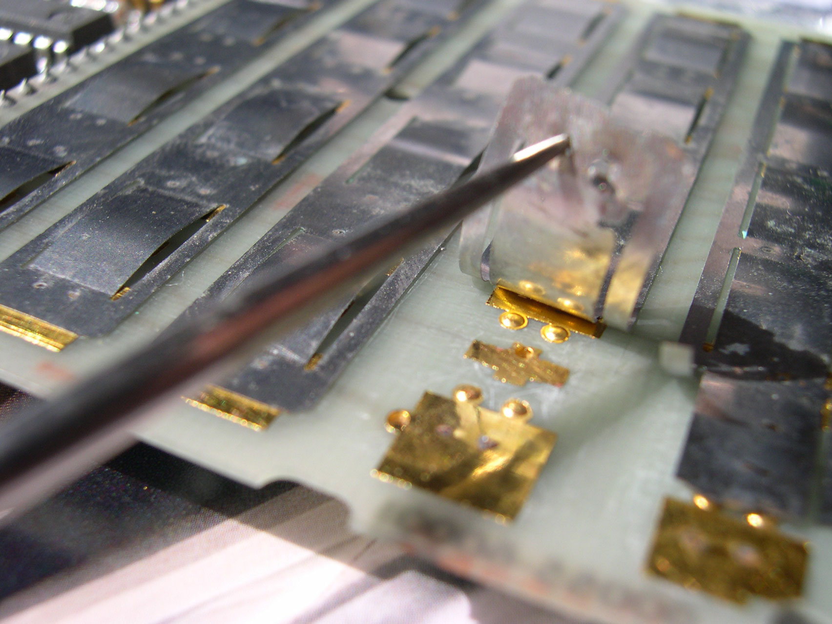
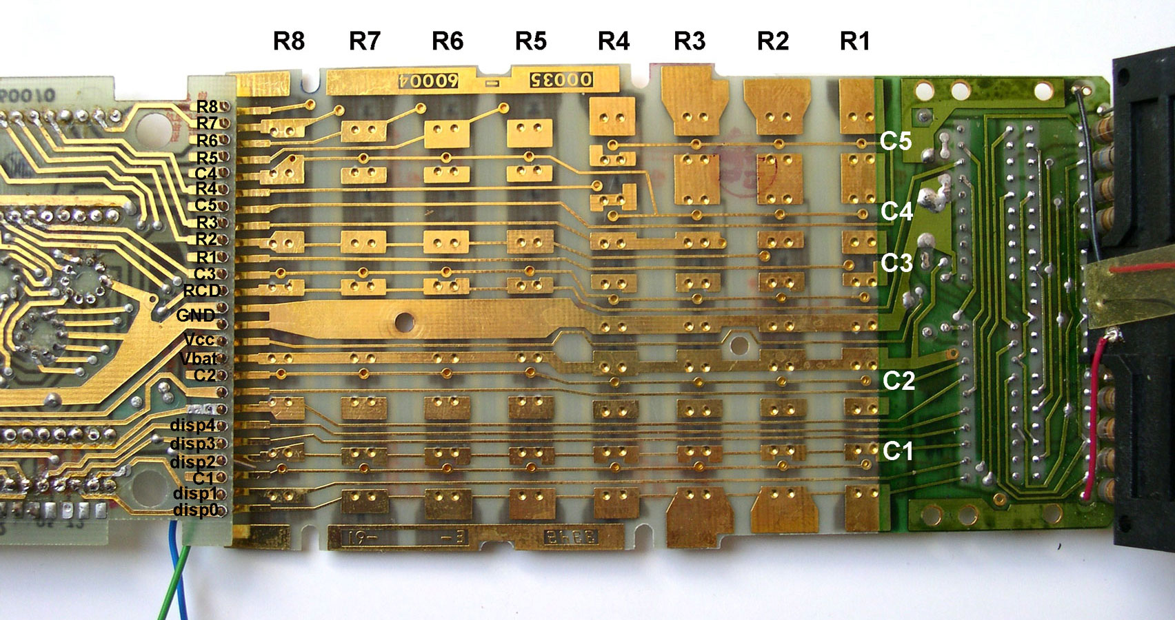
The strips (see photo 1) are spot welded to the circuit board and a matrix of traces (rows and columns) is organized. The effect of pressing a key is to make an electrical contact between one of the 8 row and one of the 5 columns.
The task of scanning the matrix-keyboard array is given to the C&T chip and more precisely to the system master counter (see the C&T page).
Its most significant three bits sequentially select one of the keyboard 8 rows lines ; every time a "1" is generated on a column, the 8 rows are scanned in turn.
"Debouncing" action is handled by the firmware.
If a contact exist at any intersection point in the matrix (by depressing a strip 'hump'), a key down signal state is saved in key code buffer and a six-bit code corresponding to the key will become a starting address for the routine executing the key function.
Photo 1 : a hump row 5, column 5 (key '9') ; the golden cross at the middle is connected to the column 5 line, on the other side. All the humps of row 5 are electrically connected by the metal strip.

photo 2 : the matrix keyboard array
On this photo, the details of the connections to the logic board appear. On each row the golden rectangles are where the humps are spot welded.

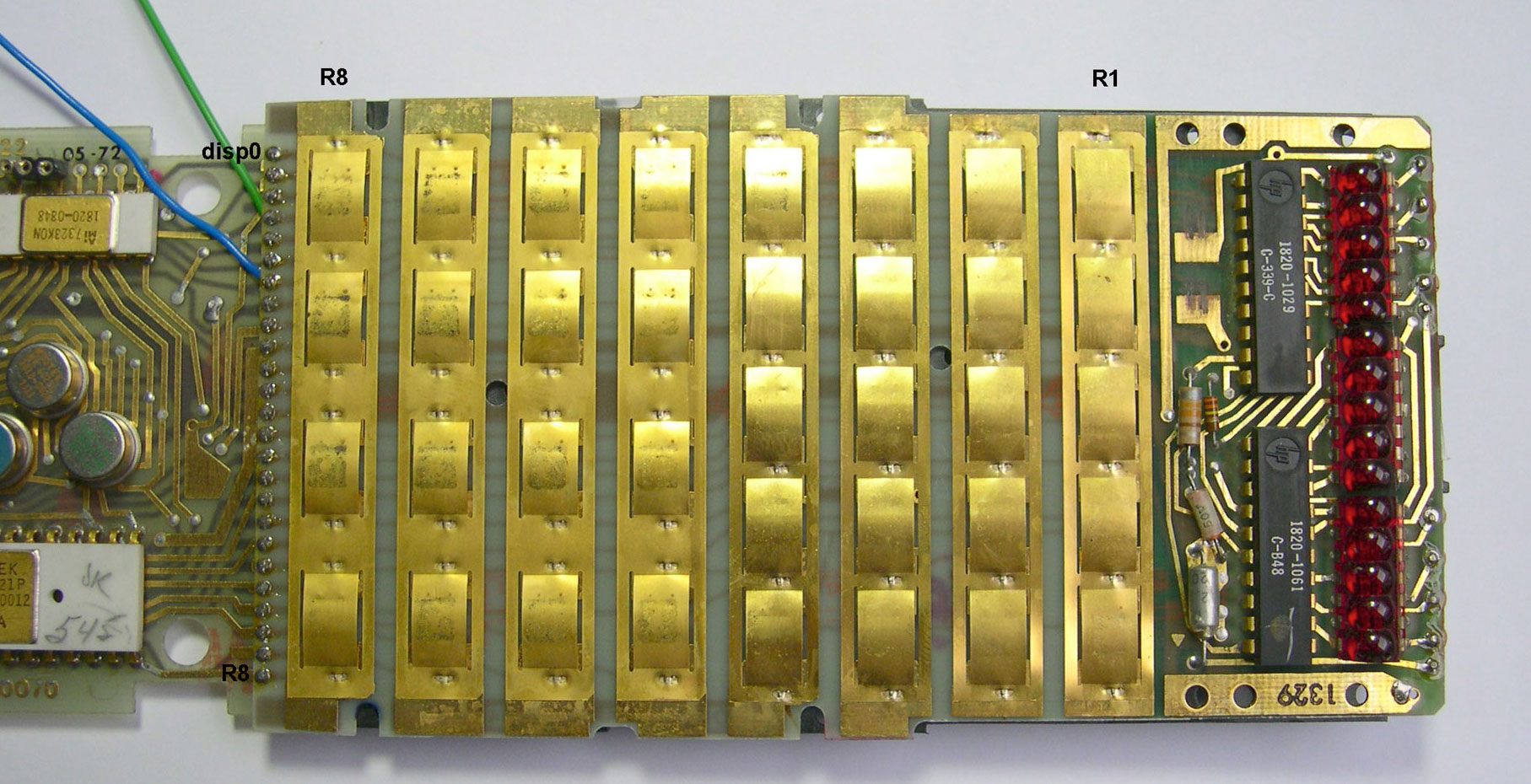
photo 3 : the keyboard sunny side up!
36 humps but 35 keys, guess why?

J. LAPORTE, Sept 1, 2009.