HP35 floating point arithmetic
Part 1 - Addition & subtraction
I will detail in this article the
algorithm used to perform in the HP 35’s ROM the 4 basic operations ![]() in
floating point representation. A good reference to read in parallel is Knuth
“The Art of computers programming” Volume 2, Chapter 4.2, and also D.J. Wheeler
et alli, “The preparation of programs for an electronic digital computer”
Addison-Wesley, 1951, that describes decimal operations.
in
floating point representation. A good reference to read in parallel is Knuth
“The Art of computers programming” Volume 2, Chapter 4.2, and also D.J. Wheeler
et alli, “The preparation of programs for an electronic digital computer”
Addison-Wesley, 1951, that describes decimal operations.
In fact, the decimal type of the arithmetic
circuits of the HP 35 and its very complete instruction set make floating point
operations particularly easy to implement.
There are 32 arithmetic and register instructions that can be combined with any of 8 options to address a portion of register or even a single digit (a total of 256 instructions).
1) Number representation.
A register of the HP35 is a 14 BCD
word (56 bits long):
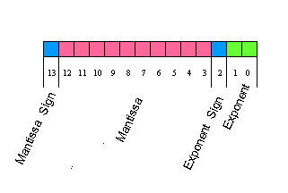
- 1 digit for the mantissa sign,
- 10 digits for the mantissa,
- 1 digit for the exponent sign,
- 2 digits for the exponent.
As D. Knuth noted, “it is
considerably more convenient to let the radix point (of a number) to be
dynamically variable or floating as the program is running” and to store its
current position.
That’s “floating point” (known also as scientific notation), for example, the
number ![]() which
is Avogadro’s number would be represented in a HP 35’s register as +
6022520000+23.
which
is Avogadro’s number would be represented in a HP 35’s register as +
6022520000+23.
It is said to be normalized since the
most significant digit (=6) is left aligned (without leading zeros as in the
equivalent number![]() ).
).
In fact, if the decimal point is “floating” in the number, the exponent being updated, it does have a fixed place in the register: in the HP 35 the decimal point appears at the right of the most significant digit as in + 6022520000 +23; this form is purely conventional.
The sign of the fraction part (since mantissa is an abuse of terminology according to Knuth) is coded with the digit "0" if positive and with the digit “9” if negative.
The exponent is coded in tens
complement notation, so that the number ![]() is
represented in normalized form as C=91250000000998.
is
represented in normalized form as C=91250000000998.
The machine uses 3 registers to represent a number, register C holds the normalized form, register A has the displayable form (floating point) A=91250000000902 and register B holds a mask to correctly position the decimal point: B=02009999999000.
The digits in the A register are in proper order and the B register is used as a masking register with digit “9” for each digit position to be blanked, digit”2” for the decimal point position and digit “0” for regular digit position.
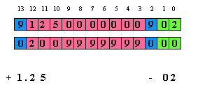
When digits in register A are gated into display, the mask in B is used to OR correctly the digits to be blanked and the decimal point, so the calculator has both a floating point and a normalized format.
00307: 1......1.. dsp3: 1
-> s8
A=91250000000902 B=02009999999000 C=91250000000998
D=00000000000000 M=00000000000000 P=c S=...34.678..b
2) Floating point addition and subtraction.
Within this code we will meet a rather classical algorithm, described in many references (see Knuth) in 3 parts:
- fraction parts aligning,
- sign processing,
- normalization.
To be complete, I will study in an upcoming article, the output formatting
routine, creating mask and display registers in the HP 35.
The first step in the process is fraction part (or mantissa) alignment and to do this exponents comparison, in order to have the biggest number in register A than can be shifted right ; the aligning mantissa maneuver consisting in shifting right fraction part and incrementing exponent.
In the example below, the addition 100 + 12.5 have been entered in reverse “Polish” logic : ”100” “ENTER”, “12.5”, “+”.
The stack – at the entry point of addition routine- is:
X = C = 1.00 102,
Y = D = 1.25 101.
Note that the 4 stack registers have
been renamed for the user’s eyes: C is named X, D is Y, E is Z and F is named T
for Top.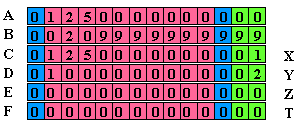
Here is what the simulator shows at entry point:
00026:
jsb l00232
A=12500000000000 B=00209999999999 C=01250000000001
D=01000000000002 M=00000000000000 P=c S=0.....678..b.
If the operation is a subtraction (”100” “ENTER”, “12.5”, “-”), the code is exactly the same but entry point is located at the previous line:
sub0: 0 - c - 1 -> c[s]
00232: stack -> a
In this case, the task of the line “sub0” is simply to exchange the sign of C
doing a nines complement.
[BP1] (references to a trace for example 100 + 12.5)
The first action of the code is to drop values from the stack, to have Y in A. Next B is zeroed and exponents of registers A and C are corrected so absolute values can be compared.
 The
exponent comparison is by adding two to exponent and sign fields of both
registers A and C.
[BP2]
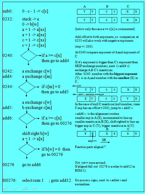
The exponent comparison a[x] > = c[x] is done twice at 0240 and at "add6" ; to have
the algorithm working correctly with negative numbers in add6, the exponents leading '0' or '9'
are removed by adding an offset (exp +- 200) to each exponent.
After 0240, the number with the smallest exponent is always in C and the biggest in A.
In fact, in the process of mantissa alignment, the smallest number fraction part (now in B) will be shifted right (division by 10) and its exponent (now in A) will be incremented.
After incrementation of exponent in A, the code branches to "add6" if alignment is not done ; without the positive exponent offset (+200) there would be no way to exit of the loop in case of negative exponent in X.
[BP3] Next in routine “add4”, the code separates the exponent and fraction parts of both numbers, introducing a third register B and putting pieces together to fraction part alignment:
A = X fraction part, Y exponent,
B = 0,
C = Y fraction part, X exponent.
[BP4] Fraction part alignment is done by “add6” routine and exit path (address 0276) will be taken when both fractional part are aligned (see flow chart).
When entering in routine “add6” the
register arrangement is as follows:
A= Y fraction part, X exponent,
B= X fraction part, zeroed exponent,
C= zeroed fraction part, Y exponent.
The shifted right fraction part is B (X) and the incremented exponent is A (number X).
[BP5] In routine “add12”, signs are processed to do the either operation “addition” (adder is at label “mpy26”) or “subtraction (label add14”).
First we restore exponent and sign exponent of C, which had been modified on entry.
Next we zero sign of A and subtract
sign C from sign of A:
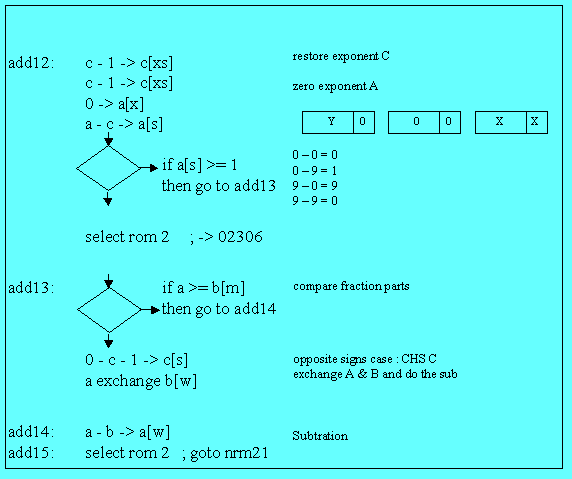 add12:
c - 1 -> c[xs]c - 1 -> c[xs]
0 -> a[x]
a - c -> a[s]
We can separate two cases:
1) same
signs:
0 – 0 = 0,
and 9 – 9 = 0,
2) opposite signs:
0 – 9 = 1,
and 9 – 0 = 9.
If both numbers have same signs, we
simply branch to address 2306, and go to the adder.
If signs are different, it is a little bit more complicated, since we must
compare fraction parts alone. This is the task of routine “add13”.
If register A fraction part is > or = than the fraction part of B, we simply perform a subtraction, and it’s over.
If register A fraction part is < than fraction part of B, we change the sign of C and exchange mantissa of A and B before performing the subtraction.
[BP6] The case of addition (02306) may seem a little bit strange, because we are using part of the multiplication code: this is just for place saving.
Address 02306 will branch to “mpy26” which is the adder (used also by multiplication routine). The Pointer P is = 12 on entry, so there will be a carry doing “c - 1 -> c[p]” and we’ll fall thru mpy28 which task is the “right scaling” (part of normalization process).
3) Normalization [BP7]
There again, the best lecture is Knuth (op. cit. Chapter 4.2.1): In this routine the “raw exponent and a raw fraction are converted in normalized form”, to cite Knuth’s words.
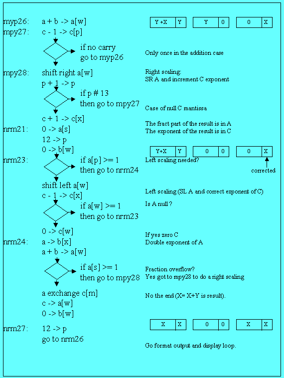
There are 2 subroutines:
1) left scaling (shift to the left and decrease exponent), in the case of non significant zeros,
2) right scaling (shift to the right and increase exponent) in the case of “fraction overflow”.
The fist case is handled by the
following lines in routine “nrm23”:
shift left a[w]
c - 1 -> c[x]
There is no comment to add, except that on exit, we go to nrm24, address 02317 ; there is though the null A register case to consider and control may fall thru nrm24, zeroing C : 0 -> c[w].
Routine nrm24’s task is right scaling. We have a fraction overflow when an addition exceeds the 10 bits length of the mantissa, and we have to a shifting right and a rounding to register A fraction part.
In this case, the least significant digit of the number in register A occupies the digit reserved for the exponent sign. So if we double the A exponent, we will have an overflow in fraction part sign. [BP8]
This is the task of the 3 first lines of nrm24:
(b[w] had been zeroed on nrm21 entry)
nrm24: a -> b[x]
a + b -> a[w]
if a[s] >= 1 then go to mpy28
…
Let’s take the example of the subtraction of 10 - .0000000004
On entry in routine “nrm24” the registers are:
02326: .1..1.1.1.
nrm24: a -> b[x]
A=09999999999600 B=00000000000600 C=00000000000000
D=00000000000000 M=00000000000000 P=c S=0.....678..b
Then, we double register A exponent and the A fraction part sign byte becomes
“1” signaling thus the “fraction overflow”.
02327: 111...111. a + b -> a[w]
A=10000000000200 B=00000000000600
C=00000000000000
D=00000000000000 M=00000000000000 P=c S=0.....678..b
In this case, we branch to “mpy28” and after one shift right of A and one exponent increment of C, we exit thru nrm21, etc.
02334: ....1.111. 0 -> b[w]
A=01000000000001 B=00000000000000
C=01000000000001
D=00000000000000 M=00000000000000 P=c S=0.....678..b
[BP9] The end of normalization is quite simple (see flow chart):
The whole result (fraction part and
exponent) is placed in C ( a exchange c[m] ) then in A
( c -> a[w] ) and B finally is zeroed ( 0 -> b[w] ).
nrm26: if s2 = 0 then go to rtn21
return
rtn21: select rom 1 ; goto rtn11
rtn11: if s1 = 0 then go to rtn12
return
rtn12: select rom 0 ; goto 00333
00333: jsb of13
....
The process will call next the output format routine (jsb of13) [BP10] whose task is to create mask and display registers (I will dedicate an article to all those service routines) and continue to end in the display and waiting loop.
Part 2 - Multiplication & Division
Paradoxically, floating point multiplication or division is much simple than addition: no fraction parts alignment, no exponents comparison, event normalization is simpler.
There again, the reference is Knuth “The Art of computers programming” Volume 2, Chapter 4.2.1, Algorithm M, p. 220 third edition.
In fact, the usual lack of space in
ROM problem leads the firmware designer to organize the code in a saving way:
part of the code for division is used for multiplication.
For multiplication, the scheme is exponents addition and fraction parts
multiplication (by repeated addition), and for division, exponents subtraction
and fraction parts division (by repeated subtraction).
Multiplication and addition are 2 number operations, so the first number (Y) is on the stack and the second (X) is on the display (C registers) when the key “*” or “÷” is pressed.
As for other routine, the numbers on the stack are in normalized form while the last entry (X) is in both forms: normalized in C and floating point in A with mask in B.
1) Common code.
The entry points for keys “*” and “÷” are naturally different, but they share a
part of code at the beginning of the process.
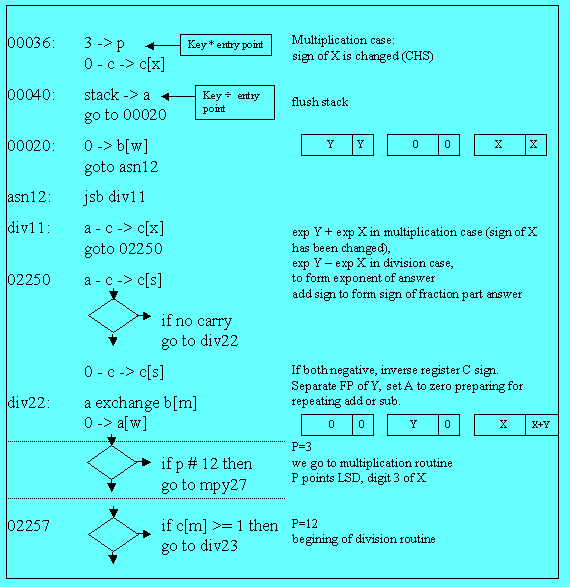
There is only on case implemented for the exponent calculation: exponent of X (C) is subtracted from exponent of Y (A) ; if we are doing a multiplication, we just change the sign of X doing a tens complement on the C register.
Another difference is that pointer P is initialized with 3 in the case of multiplication (explanation later) and with 12 –as usual- in the case of division.
The common code starts at address 00040: we just flush the stack (D -> A) and call routine “div11” that will deal with exponents for both cases (see the commented trace for 2 examples 2.5*3.6 and 2.5/3.6. and the flow chart of the common part).
At address 02250 we test if both fraction parts (of A and C) have a negative sign. If yes, we correct sign of C.
Next at “div22”, we separate fraction part of Y which is placed in the B register (fraction part of X and exponent of the future result is in C.
Register A is set to zero, in preparation for repeated addition (multiplication) or subtraction (division).
Finally, we test if the value of P is # 12 (in fact = 3), if so, we go to the multiplication entry point:”mpy27”. Otherwise, we continue to the first address of division routine (02257).
2) The multiplication routine.
The multiplication core routine is very simple: just like with “pencil and paper”.
On entry, P (= 3) points the least significant digit of the fraction part.
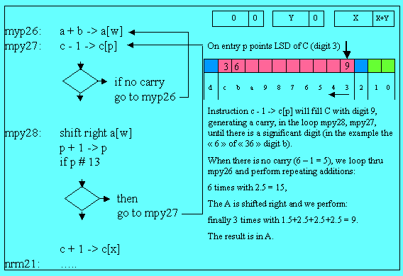 We
first execute c – 1 -> c[p] generating a carry since the third digit of X is a
zero (the resulting digit being “9”)[BP1]. We continue thru “mpy28”, incrementing p
and looping to “mpy27”.
This loop will replace all the trailing zero of X by digit “9” and will stop at the first non zero digit.
When we reach the “6” of “36”, there is no carry in “mpy27” and we branch to “mpy26” (the resulting digit b being 6 – 1 = 5. We do the addition at “mpy26” 6 times 2.5 and the result is 15. (in A) [BP3].
Next A is shifted right and the
partial result is 1.5, of course.
Finally, we re enter the same process to do 3 times the addition 1.5 + 2.5 + 2.5
+ 2.5 giving the final result 9 (in register A).
After correcting the exponent, we go directly to normalization (nrm21). This is
very straightforward.
3) The division routine.
The division core routine is as simple, but repeated additions become subtractions.
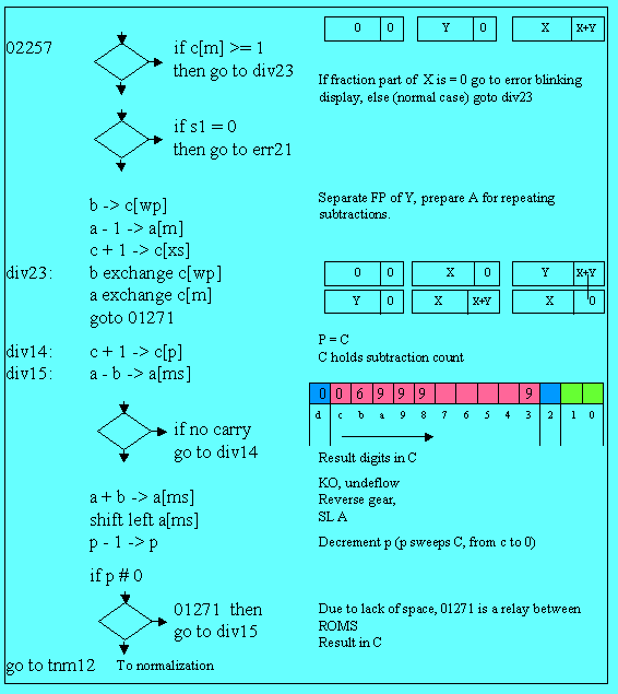 We
first do a test for error condition: if we are about to make a division by zero,
we go to the error blinking display.
Next instructions (if s1#0) are used only by trigonometry (computing cos(0)).
The core division routine begins at label “div23” [BP1]: fraction part of X is placed in register B and fraction part of Y in register A, in preparation for repeated subtractions.
On entry, pointer P = 12 thus pointing the beginning of register C, which will holds digits of the result.
Entry point is at address 1271: that
provides a cheap relay to ROM 1.
We are now at address “div15” in the core divide loop [BP2] and we do the first subtraction a – b -> a[ms].
We loop to “div14” till there is a carry (we can’t subtract anymore). In each loop we store the result doing c + 1 -> c[p]: so C digit p (loop count) is the current digit of the result.
Follow, please the trace while reading.
When there is a carry in a subtraction, we have gone too far.
We reverse gear doing a + b -> a[ms] [BP3] to restore previous result, we shift left register A and decrement pointer P, to process the next digit of result.
Before going to “div15” to re start repeated subtractions for this new digit, we just test if p#0 otherwise that’s over and we go to label “tnm12” which is a simple byway to normalization with the result in register C.
The process is almost simple as the “pencil and paper” method without “having to guess how many times one number goes into another” though: the calculator will try to make as much partial subtractions as possible, until underflow.
Jacques Laporte
January 3, 2006, revisited Dec. 2008.
See also : J. Laporte
"Digit by digit Methods" June 1976