|
|
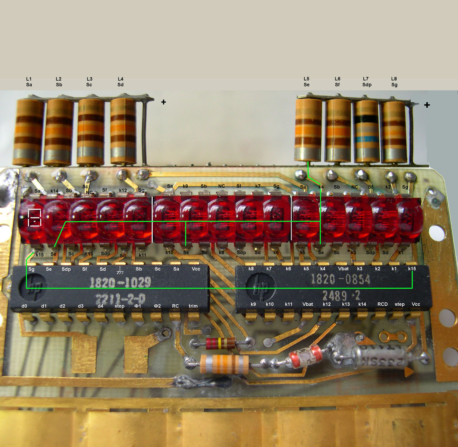
HP-35 Display Schematic |
This is the HP-35 display schematic, the 8 inductors being folded.
HP Associates developed for the project a magnified 5-digit cluster in a 14-pin package.
There are 3 clusters = 15 digits.
In a cluster there are 8 anodes (7 segments + 1 decimal point) and 5 cathodes, that's only 13 pin ; one pin (pin #11) is not connected internally.
On the photo, clusters are separated by a white line.
The pinout of each LED cluster, Anode driver and Cathode driver is indicated.
Sx means Segment x (anode),
ky means Cathode y.
According to the thoery, all the same 3 anodes are wired together across clusters.
There is a link 1->3 between the Anode driver output (Sx) and the corresponding anodes (1 per cluster).
Cathodes are linked one by one (1->1) : one pin of the Cathode driver corresponds to one pin of the 3 LED cluster block.
To keep the schematic clear, I have only represented 1 anode wiring 'Se' Segment 'e' and one cathode wiring 'k15'.

J. LAPORTE, Aug 28, 2009