|
|
The Anode & Cathode drivers |
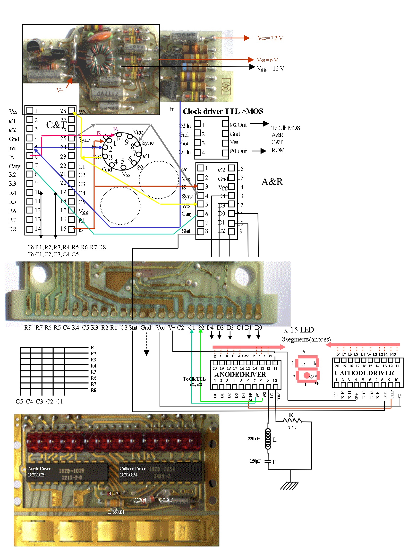
On the 35 (and the Classics series) the Display-Keyboard PCA is linked to the main logic board via a 25 pins connector (see photo below).
This connector is 'bi-directional' ; the signals or levels from the Display-Keyboard PCA to the main logic board are :
- the power voltage from the batteries (3*1.2V DC) or from the wall adapter (around 4V DC),
- the 200 khz main 2 phase clock (TTL levels),
the signals from the main logic board to the Display-Keyboard PCA are:
- the 5 lines from the C&T scanning the keyboard columns (C1 to C5),
- the 8 lines from the C&T scanning the keyboard rows (R1 to R8),
- the 5 lines from the A&R partially decoding the display (D0 to D4),
- the 'start' signal from the A&R to the Cathode driver,
In common:
- the common ground
- the Vcc line.
The fig 1 below helps positioning every sub-system. I will give elsewhere a detailed schematic of the wiring. You can also see the description of the keyboard logic here.

The Anode driver (part 1820-1029) is a bipolar circuit that has 2 purposes:
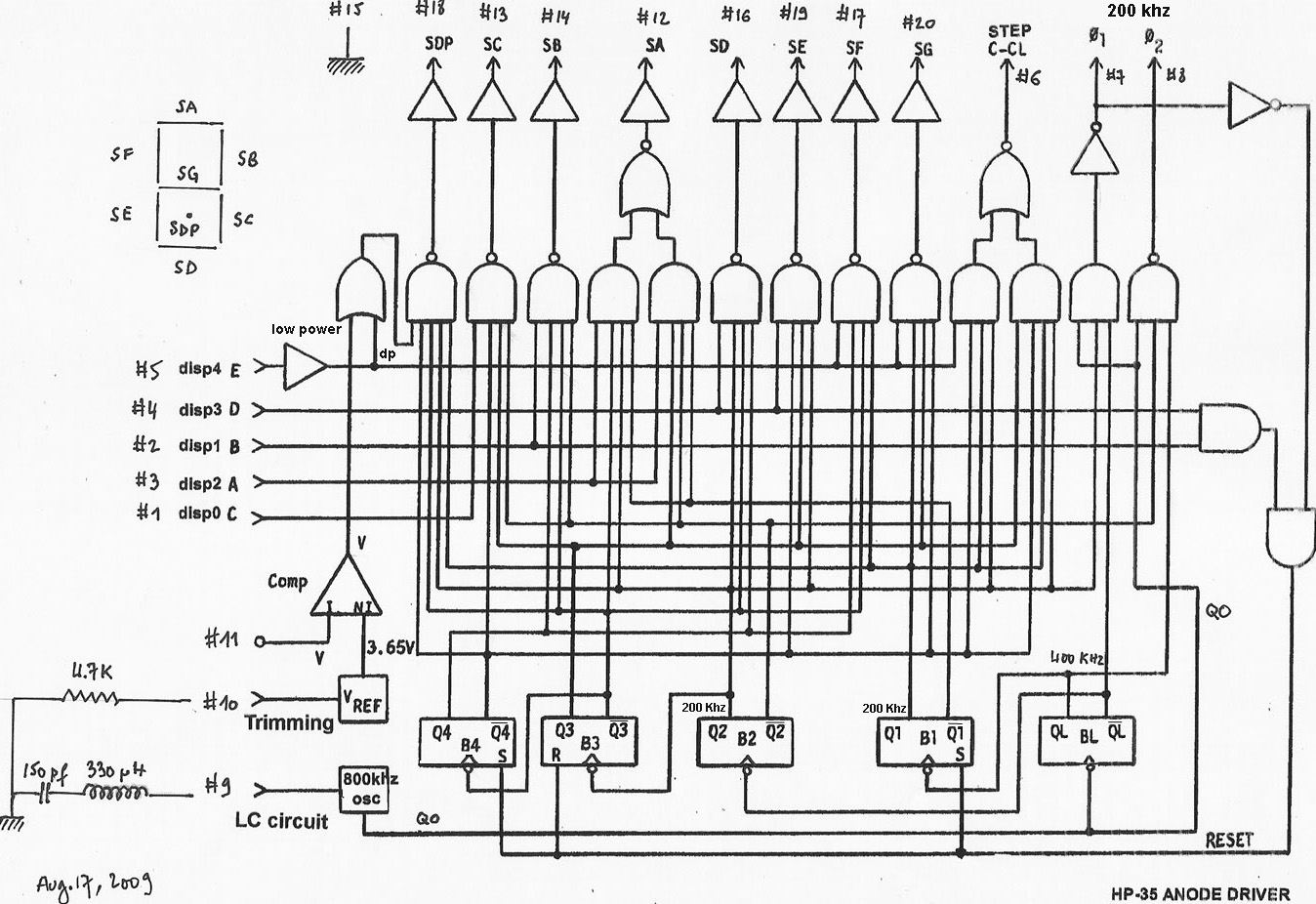
- it is the clock generator for the calculator and uses an LC series circuit to sest the frequency to 800khz divided by 4 by a flip-flop stage (see fig 2),
- it decodes the 5 lines D0 to D4 from the A&R ; the signal for each of the 8 segments + the decimal point being time shared during the 'digit time'.
The LC circuit for the Anode Driver is : L = 330 uH, and C = 150 pF making a frequency of 800 Khz approximately. If a quartz is mounted as on the HP-55, the exact frequency is 784khz. On an old HP-35 the LC components are aging, so the measured frequency is not the one given by theory. But it works just as well.
The 2.2uF capacitor is decoupling Vbat while the 4.7 resistor is trimming the reference voltage, VREF on fig. 2, which is the reference input of the comparator for the low battery voltage detection turning on all the decimal points.
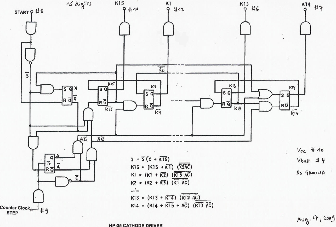
The pinout for Anode driver is given in fig 1 and its internal correspondence is given in fig 2 for the AD and in fig 3 for the CD.
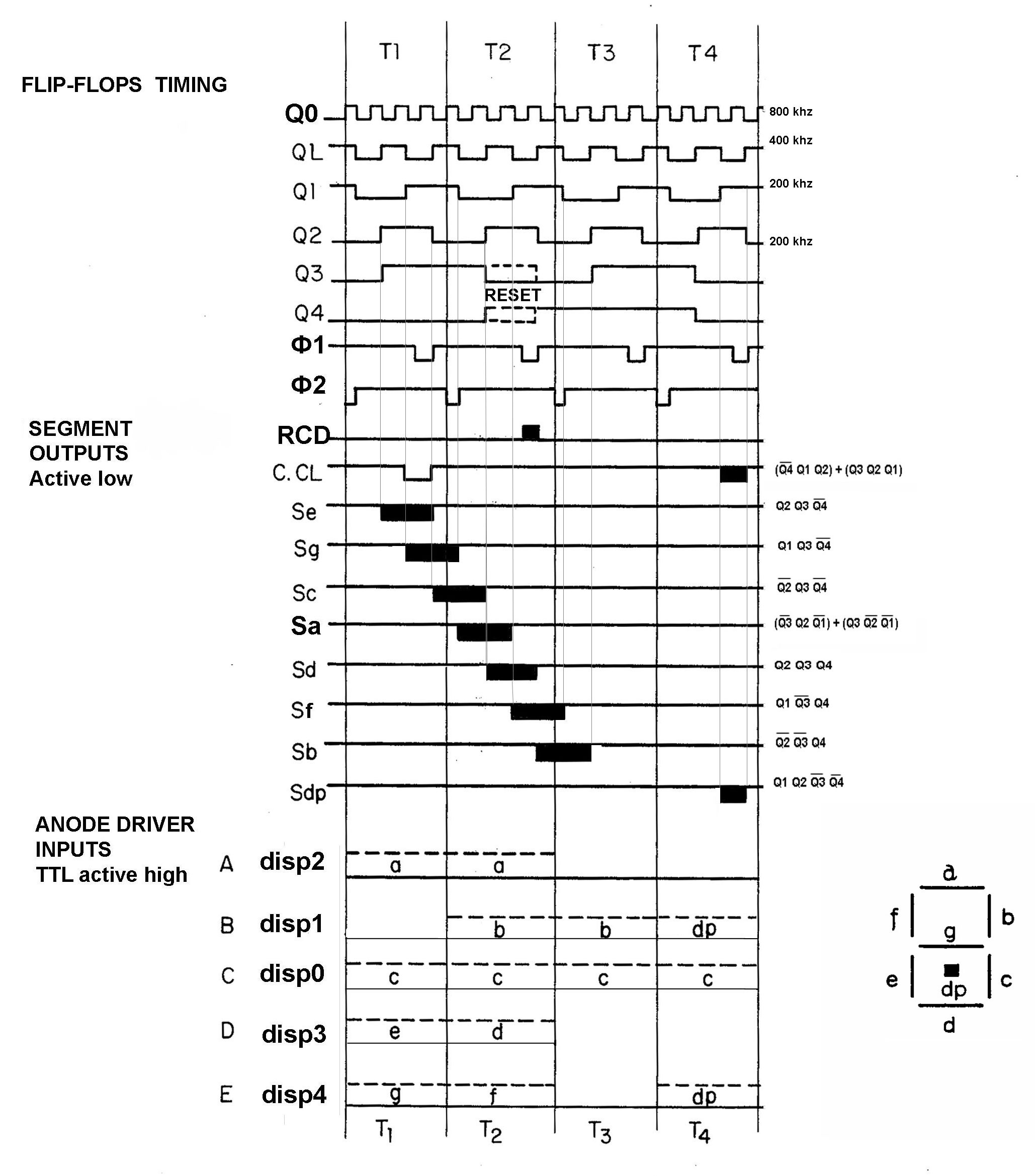
Here is an accurate timing diagram, divided in 3 parts:
- the timing on the flip-flops inside the anode driver, dividing the main 800 khz frequency in 400 khz, 200 khz etc/ The references Q0, QL, Q1, Q2, Q3, Q4 are coherent and checked with the anode driver schematic.
- the timing of the anode levels (segments) : active LOW, the output BJT is sinking the LED current.
- the TTL level inputs to the anode driver (note this is not BCD data, but multiplexed signals sent by A&R).
Only 2 line are time shared D and E : 5 segments are concerned 'e', 'd', 'g', 'f', 'dp'.
A counter-clock (STEP or C.CL) is generated by the anode driver 'decimal point' logic (10th line).
Boolean expression are given for each segment to enable the relevant time window. I have drawn vertical time-lines, so expression can be checked with the anode driver schematic. The reset logic (RCD) is documented line 5, 6, 8, timing 01 (A&R gives a reset forcing D and B high during T2 (Q2 Q3 Q4) at 01).

The extra character (15 in a word of 14 digits) is the decimal point which is derived from the presence of digit '2' in the A&R register B at the '.' position. The decimal point signal can come also from the comparator, when the power voltage is lower than the reference (It does not depend on a A&R line, then all the points light).
When the A&R's display decoder recognizes BCD two ('2') in the register B, it signals this situation to the anode driver placing logic '1' on its inputs B and E during bit time T4. Then the anode driver will excite the 'decimal point' anode and raise the STEP (C.CL) signal to make the cathode driver point the nexet position (all remaining digits are shifted-action of the cathode driver).

The Cathode driver (part 1820-0854) is also a bipolar circuit and consists of a shift register for scanning the 15 display and of 15 cathodes switches. The position scanning moves from digit to digit following the signal STEP from the anode driver.
Each digit is addressed once in the word time. The sweep is restarted when the START signal comes from the A&R at the start of the word time.
The cathode driver can be check easily applying low level Vbat to a cathode pin (K15, pin11 for example).

J. LAPORTE, Aug 20, 2009