HP35 inverse trigonometric algorithm
I will detail in
this article the algorithm used in the HP 35 to compute inverse trigonometric
functions:
![]() ,
,
![]() and
and![]() .
.
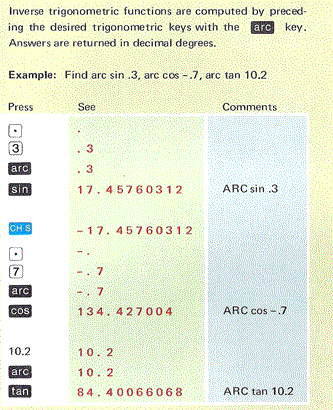
A prefix key named "arc" is used, as shown in the user manual p.19 is used and than angle is returned in degrees.
I assume that my
previous article on the HP35’s logarithm and direct trigonometric functions has
been read, just to avoid repetition.
1) Vectoring with CORDIC.
 In
his original work paper published in 1959, Jack Volder covered in depth the
subject for a "bit serial" computer.
The architecture described can work in two modes:
1) “rotation”,
- the input is an angle θ,
expressed in vector components (X0,
Y0),
- rotations αj
tends to diminish the residual angle θ
– α0
– α1
…- αj
to zero,
- ouput is Yn and Xn, so that, Yn / Xn = tan(θ).
2) “vectoring”,
- the input is a vector (X0,
Y0),
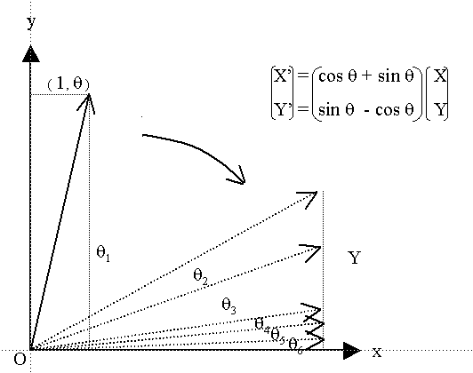
- rotations through whatever angle tends to align the resulting vector to the X
axis, minimizing, thus, the Y component,
- the output being an angle Zn
= tan-1
(Y0/X0).
There is here a common misunderstanding I want to clear away (based on a first reader’s feedback from my previous articles).
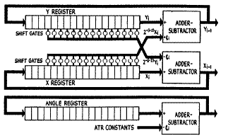
The Volder’s approach cannot be implemented as is, in a small calculator such as
the HP 35.
 In
Volder’s own words: “CORDIC is an entire-transfer computer; it contains a
special serial arithmetic unit consisting of three shift registers, three adder-subtractors,
and special interconnections”.
The case of the HP
35 is different.
Ten years have passed and the firmware designer can use a full BCD arithmetic
unit totally controlled by micro-program; that is why he preferred, there again,
to follow the two pass pseudo-division & pseudo-multiplication approach designed
by Meggitt (Cf. ref 1 p. 216).
The Meggitt’s
presentation does not follow the trigonometric classical scheme for the
successive rotation formulas, but uses the complex numbers notation. This
extension to the complex domain is just another paradigm.
For the direct trigonometric functions, Meggitt simply wrote (op. cit. p. 223,
eq. 65):
![]() where
where![]() is
a complex number and
is
a complex number and
![]() a
real.
a
real.
Note that the multiplication of complex numbers is another way to express the
composition of rotations. Then taking the complex logarithm of the equation,
Meggitt could write (op. cit, p. 223, eq 64):
![]()
and simply
![]() (
(![]() ).
).
Remember that the
process was: by pseudo division (eq. 64) we can compute the set of exponents
![]() and
by pseudo multiplication (rotations) we simply formed equation 65.
and
by pseudo multiplication (rotations) we simply formed equation 65.
For the inverse trigonometric function, we will indeed use the inverse process.
We start from a
point in the plane
![]() and
we rotate the vector clock wise to the x axis, minimizing thus the Y component
and counting the number of rotations (
and
we rotate the vector clock wise to the x axis, minimizing thus the Y component
and counting the number of rotations (![]() )
for each angle
)
for each angle
![]() .
.
Meggitt wrote:
![]() (eq
21, p. 216)
(eq
21, p. 216)
which expresses clock wise (cf. the negative sign) rotation composition in the
complex number notation.
Then he took the complex logarithm and the imaginary part, and had:
![]() (eq.
23, p. 216).
(eq.
23, p. 216).
The process is there
again in two parts: we’ll find numbers
![]() by
pseudo-division first, and then we’ll compute
by
pseudo-division first, and then we’ll compute
![]() by
a pseudo-multiplication “using stored values for
by
a pseudo-multiplication “using stored values for
![]() ”.
”.
The order of part1
and part2 are reversed; in part1 (compared to the direct trigonometric case) ;
we process by to successive rotations in such way as to make the imaginary part
of equation 21 as small as possible ; minimizing the Y component while keeping
it positive (starting with
![]() and
and
![]() ).
).
The use of the
pseudo-division process is quite similar as in the case of logarithm, but the
pseudo divisor
![]() is
different (eq. 27, p.216, comp. eq.7, p.213).
is
different (eq. 27, p.216, comp. eq.7, p.213).
At the end of part1, we have a set of ![]() integers
as result.
integers
as result.
The part2 of the process is straightforward, applying equation 23 exactly as done in the logarithm case.
To be quite clear,
I’ll return to the trigonometric paradigm: in part 1, we make successive
rotations to drive Y component close to zero. The angles of rotations are chosen
to requires only shift and add to process (![]() ) :
) :
![]()
The pseudo quotient
![]() means
exactly how many times a rotation j is performed.
means
exactly how many times a rotation j is performed.
The formulas for rotations are the same as for direct trigonometric function except the sign: we rotate clock wise.

![]()
![]()
Recurrence relations are also similar except for the sign:
![]()
![]()
It is in fact, very similar to the Volder’s original implementation, except for 3 points:
- constants are decimal
![]() and
not
and
not
![]() ,
,
- calculations are done in 2 passes, Cordic using simultaneously 3 adders-subtractors
computes in 1 pass (of multiple rotations),
- Y component never gets negative.
2) Pseudo division: Cordic Rotations
The recurrence relations implemented are derived directly from the Cordic rotation equations given above:
![]()
![]()
Component
![]() is
getting smaller all over the process, so to keep accuracy a small rewriting is
convenient.
is
getting smaller all over the process, so to keep accuracy a small rewriting is
convenient.
Introducing![]() ,
the previous relations now write:
,
the previous relations now write:
![]() (eq 1)
(eq 1)
![]() (eq
2)
(eq
2)
These are Meggitt’s equations n° 27 (p. 219) and that is exactly what is coded in the HP35’s ROM.
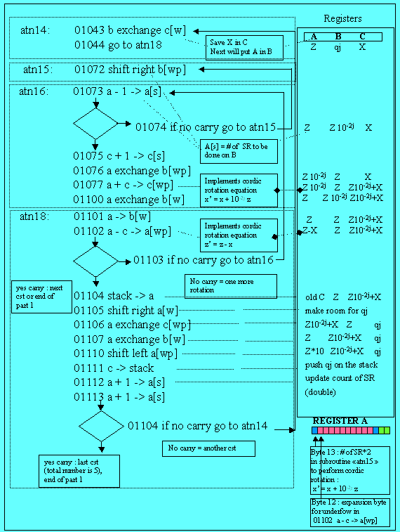
Here is the flow-chart of part 1 (pseudo division) ; the trace for arc tan(20) is simple to follow, provided that my previous articles have been read.
 I’m
going to detail only one rotation: it is a repetitive process.
At [BP2] in the
trace, we have made a first rotation![]() .
.
The result is Z=19. (register B) and X=21. (register C).
As in the logarithm or tangent routines, byte 13 of register A is reserved for the shift right (SR) count and byte 12 for underflow expansion.
At [BP2A] address 0114, we have a carry trying to rotate by another 45° angle. So we are changing to constant tan-1(0.1); the code is at label atn14. We exchange B and C to use B for shifting operations, and we go to atn18.
Then, at [BP2B], the
code implements equation 1 for the Cordic![]() :
:
01102: a - c -> a[wp]
thus the new Z is in A, the old in B and X is in C.
We test if this operation makes a carry, if yes we must change constant. If no, we get back to atn16.
At [BP2C], the
routines atn15 and atn16 look like eca21 and eca22 of the logarithm algorithm
since instruction a + c -> c[wp] which implements equation 2 of the Cordic (![]() )
is done on shifted values. A difference is that the number of SR is doubled.
)
is done on shifted values. A difference is that the number of SR is doubled.
When B is correctly shifted to the right (depending on the parameter j), we perform equation 2, and update the count of qj in c[s]. That’s one loop.
If we do have a carry at address 01103, then that’s either the end of the loops for the constant (the current j) or the end of part 1.
We pull from the stack the previous value of C (set of qj) and we store the result we just got for the current j, we mix them and store the whole result back onto the stack.
Last 2 things, we
multiply by 10 the result Z, to save accuracy and we make a test to determine if
it’s the end of part 1. For that, since we use only 5 constants, we just have to
double the count of SR:
01112 a + 1 -> a[s]
01112 a + 1 -> a[s],
luckily we have to do it even if we there is no carry, to compute the next
constant.
Further, in [BP3],
we have finished the pseudo division process, in our example the
![]() 77371
and the final components are: Y=0.0017656039685, in B (left aligned), and
X=29.327744737 in C.
77371
and the final components are: Y=0.0017656039685, in B (left aligned), and
X=29.327744737 in C.
But there is a
residual angle that has to be taken care of. Since it is very small, we’ll start
the second part with ratio Z/X which is very close approximation of this small
angle![]() .
.
For this calculation (![]() )
we call the division floating point routine. At [BP4] the division is done and
the normalized result is: 0.602025134 (left aligned) and 6.02025134 10-5
in floating point.
)
we call the division floating point routine. At [BP4] the division is done and
the normalized result is: 0.602025134 (left aligned) and 6.02025134 10-5
in floating point.
The calculation
trace of part 1 with Mathematica gives:
![]()
![]()
![]()
![]() etc.. down to
etc.. down to
![]()
![]()
![]()
(see the Mathematica trace here and the Mathematica note book here)
3) Pseudo multiplication
Now can process part 2 which looks like the process for logarithms (the constants loaded from ROM being different).
We compute in radians (the following constants are stored in radians);
![]() arc tan(0.0001),
arc tan(0.0001),
![]() arc tan(0.001),
arc tan(0.001),
![]() arc tan(0.01),
arc tan(0.01),
![]() arc tan(0.1),
arc tan(0.1),
![]() arc tan(1) = pi/4,
arc tan(1) = pi/4,
and we start with
the left aligned remainder Y/X and we form equation 23 (in fact we sum up all
small angles).
At [BP5], the result (the angle) is in A normalized 1.520837931000.
We now have to
convert this value from radians to degrees multiplying by
![]() ;
we first load
;
we first load
![]() ,
double it so we can divide the angle by
,
double it so we can divide the angle by
![]() [BP7]
and finally multiply by 90 to have the result in degrees, which after
normalization is = 87.137137594757
[BP7]
and finally multiply by 90 to have the result in degrees, which after
normalization is = 87.137137594757
A=08713759476001 B=00200000000999 C=08713759476001
The result with
Mathematica:
![]()
4) Other inverse functions
The inverse
functions for![]() ,
,
![]() are
directly derived once
are
directly derived once
![]() has
been generated, following the simple relations
has
been generated, following the simple relations
![]() and
and
![]() :
:
- the code for
![]() begins
at address 01015, then mpy21, add10, sqt11, asn12, div11 to compute
begins
at address 01015, then mpy21, add10, sqt11, asn12, div11 to compute
![]() and
then atn11 as above,
and
then atn11 as above,
- the code for
![]() begins
at 01152 where we compute
begins
at 01152 where we compute
![]() (see
simple trace
for both cases).
(see
simple trace
for both cases).
Enjoy and please,
give me feedback.
J. Laporte, Thursday, 22 December 2005.
revised 03/04/06
1) J.E. MEGGIT, Pseudo Division and Pseudo Multiplication processes, IBM Journal, Res & Dev, April 1062, 210-226. See trigonometry functions p.225.