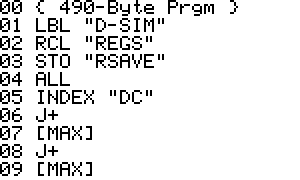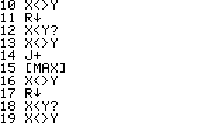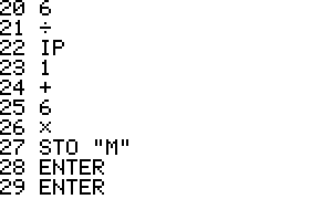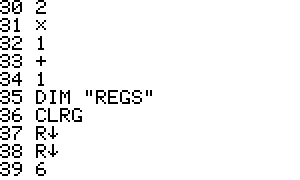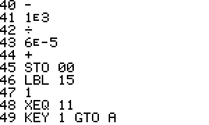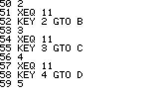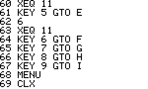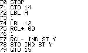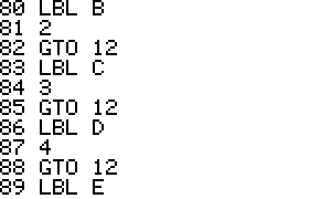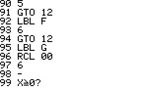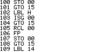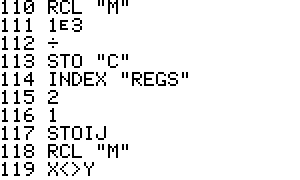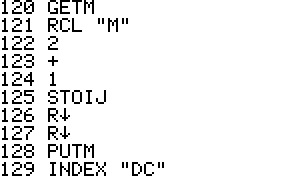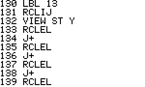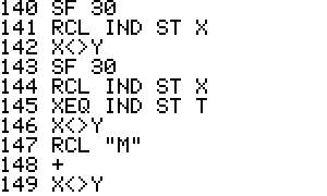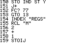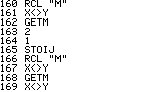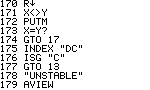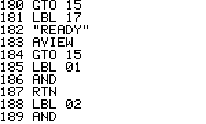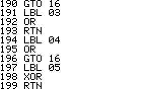
Digital circuit simulator - Simulates circuits with digital components.
Input:
An N*4 matrix called: "DC" with the circuit description. Each line in the matrix contains one component.
Column 1 in the
matrix indicates the type of component (1 to 7),
Column 2 indicates
the output node of the component
Column 3 and 4
indicates the input nodes of the component.
Component types:
| AND | 1 |
| NAND | 2 |
| OR | 3 |
| NOR | 4 |
| XOR | 5 |
| XNOR |
6 |
| Inverter |
7 |
The input node of an inverter is placed in column 3.
Input Matrix DC:
|
1 |
3 |
7 |
8 |
|
2 |
4 |
1 |
8 |
|
3 |
5 |
2 |
7 |
Component |
Output node |
Input node |
Input node |
|---|
Usage:
After starting D-SIM the following menu appears:


When the simulation is ready:

In case of a unstable circuit:

Reasons for an unstable circuit are:
1: Illegal operations with a flip-flop. See example 2.In an Unstable situation the values of the nodes is garbage. Pressing R/S again will give different results.
Example 1:
1 of 4 decoder:

Input matrix ("DC"):
|
1 |
3 |
7 |
8 |
|
1 |
4 |
1 |
8 |
|
1 |
5 |
2 |
7 |
|
1 |
6 |
1 |
2 |
|
7 |
7 |
1 |
|
|
7 |
8 |
2 |
The truth table:
|
Inputs |
Outputs |
||||||
|
1 |
2 |
3 |
4 |
5 |
6 |
7 |
8 |
|
0 |
0 |
1 |
0 |
0 |
0 |
1 |
1 |
|
1 |
0 |
0 |
1 |
0 |
0 |
0 |
1 |
|
0 |
1 |
0 |
0 |
1 |
0 |
1 |
0 |
|
1 |
1 |
0 |
0 |
0 |
1 |
0 |
0 |
Node 1 = 0 and Node 2 = 1;

Press R/S.


Node 5 is 1; Node 7 is 1
Example 2:
RS Flip-Flop:

Input matrix ("DC"):
|
4 |
3 |
1 |
4 |
|
4 |
4 |
3 |
2 |
The truth table:
|
Simulation step |
Inputs |
Output |
Output |
Remark |
|||
|
1 |
2 |
3 |
4 |
3 |
4 |
||
|
1 |
0 |
1 |
0 |
0 |
1 |
0 |
Set Q |
|
2 |
0 |
0 |
1 |
0 |
1 |
0 |
Memory |
|
3 |
1 |
0 |
1 |
0 |
0 |
1 |
Reset Q |
|
4 |
1 |
1 |
1 |
0 |
0 |
0 |
|
|
5 |
0 |
0 |
0 |
0 |
1 |
1 |
Unstable |
|
6 |
1 |
0 |
1 |
1 |
0 |
0 |
Reset Q |
On such a flip flop it is not allowed to change both inputs from 1 to 0. In a real circuit one input is faster than the other one. That one will ‘win’. In a simulation both the inputs are change on the same moment. This will result in an Unstable situation.
Binary files for emulators:
Raw binary: dsim.raw
Binary for HP-42X: dsim.42x
